

Flow Nozzle ISO 1932
The ISA 1932 flow Nozzle is precision machined flow element as per various International Standards such as BS 1042 and ISO 5167 part 3, This flow element is used for high velocity, non-viscous, erosive flows which would wear or damage an orifice plate, when low permanent pressure loss is desired and high operating pressure and high operating temperatures are involved. Typically, nozzles have a large capacity and well accuracy with high velocity flows. The required straight inlet section is much less than an orifice and the discharge coefficient of the nozzle is such that a nozzle can measure approximately 55% higher flow rates than an orifice plate with a similar beta ratio and design differential pressure. ISA 1932 Nozzles have a smooth centrical inlet leading to a throat section with sharp outlet. The length of the ISA Nozzle depends on the Beta-Ratio. The lower the ratio the less the length. Corner pressure taps upstream and downstream of the nozzle shall be used. These can be either single taps or annular slots. Depending on customer requirements, the typical 1/2 in. or 3/4 in. tappings have a butt or socket weld, screw thread or flange connection. Available in wide variety of materials (A105, SS316, F12, F22,…)
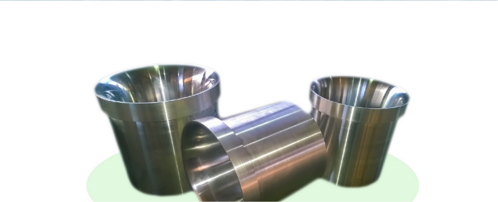
Flow Nozzle Long Radius
The Long Radius Flow Nozzle are manufactured acc. the ASME Standard and the flow calculation is done according to the ISO 5167- Part 3 and BS 1042. This type of flow nozzle is mainly used when low permanent pressure loss is desired and high operating pressure and high operating temperatures are involved. There are two types of long radius nozzles: High Beta nozzles (0,25 ≤ β ≤ 0,8) and Low-Beta nozzles (0,20 ≤ β ≤ 0,5). Long Radius Nozzles have a smooth elliptical inlet leading to a throat section with sharp outlet. The length of the Long Radius Nozzle depends on the Beta-Ratio. The lower the ratio the less the length. The Long Radius Nozzle is achieved as complete meter run with a weld-in unit or pin type which depend on the design pressure and temperature. The upstream/downstream tap locations are designed to be at D and D/2 from the inlet face of the nozzle based on the ISO 5167 standard and the end connection of tit can be supplied both in flange or butt welded type. Depending on customer requirements, the typical 1/2 in. or 3/4 in. tappings have a butt or socket weld, screw thread or flange connection.